
My Projects
Height-Adjustable System for Agricultural Robot
Context and Challenge
For the company OSIRIS Agriculture, the objective was to design and integrate a height-adjustable suspension system for their crop-irrigating robot. This mechanism had to allow the robot to pass over tall plants without damaging them, while maintaining a compliant road transport profile.
Objectives
- Increase the ground clearance of the robot.
- Ensure road transport within the regulatory width and height limits.
My Role
- State of the art and selection of the most suitable lifting concept.
- Mechanical sizing and validation of the chosen system.
- 3D design and integration into the existing digital mock-up.
- Mechanical strength simulation and analysis using ANSYS Workbench.
Methodology
- Initial discussions with the client to clarify technical and functional requirements.
- Research and benchmark of existing lifting mechanisms.
- Concept evaluation through comparative analysis tables.
- 3D modeling and parametric design using CATIA V6.
- Numerical simulation and stress analysis with ANSYS Workbench.
Technologies & Tools
Mechanical sizing: supplier datasheets, strength of materials calculations.
Software used: CATIA V6, ANSYS Workbench, Excel, Word.
Lessons Learned
Strengthened skills in project management, mechanical sizing, and simulation-based validation.
Rugby Target Project
Context & Goal
In partnership with Stade Rochelais, the goal was to design a simulation device to optimize lineout training by faithfully replicating players’ movements and dynamics.
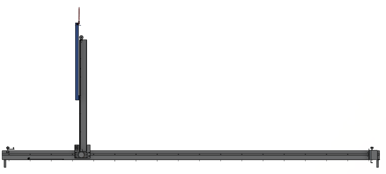
Front view
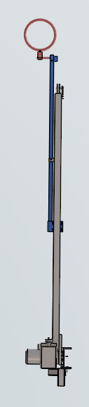
Right view
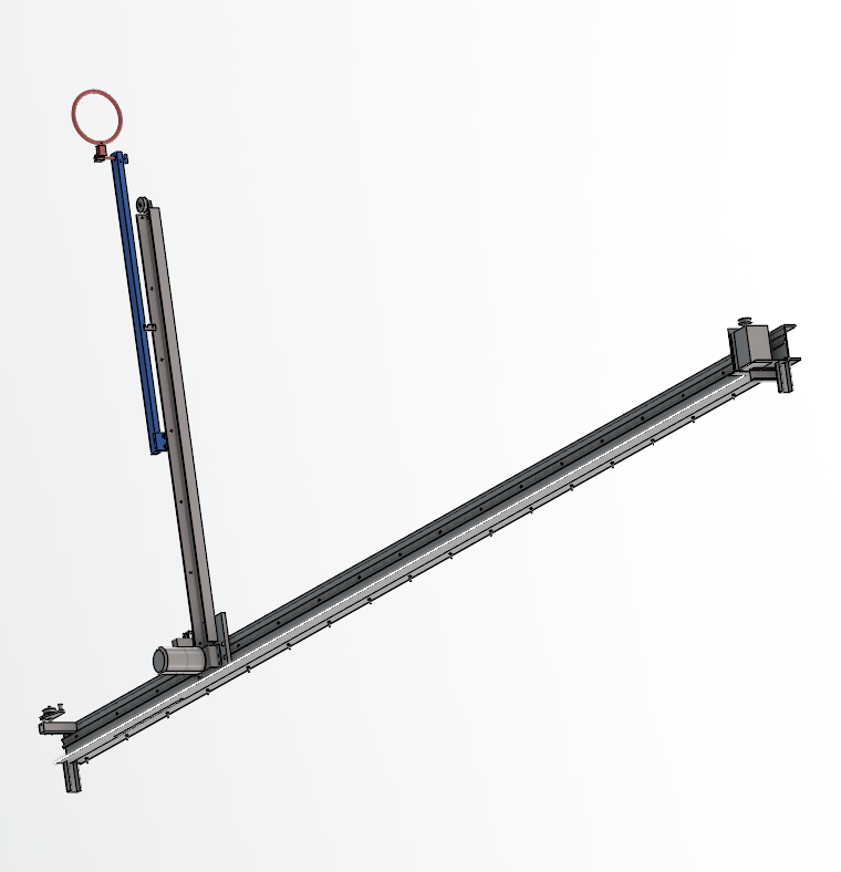
Isometric view
Objectives
- Replicate hookers’ movements during lineouts
- Provide real-time feedback on throw accuracy
- Improve players’ responsiveness
- Diversify players’ strategies
My Role
- Horizontal motion of the target: from design to sizing
- Component selection: rails, rollers, fasteners
- Sizing of rollers, fixing screws, and transmission belt
Methodology
- Client discussions to clarify needs
- Survey of existing solutions and limitations
- Brainstorming, comparative decision table
- Calculations and 3D modeling in CATIA V6
Technologies & Tools
Sizing: Supplier datasheets, strength of materials calculations.
Software: CATIA V6, Excel, Word.
Lessons Learned
Deeper project management, mechanical sizing, and teamwork across disciplines.
Prosthesis Project for Post-Cubital Amputees
Context & Goal
At the request of an occupational therapist, we designed a forearm prosthesis intended for cycling—adjustable and adaptable to different patients, to facilitate rehabilitation.
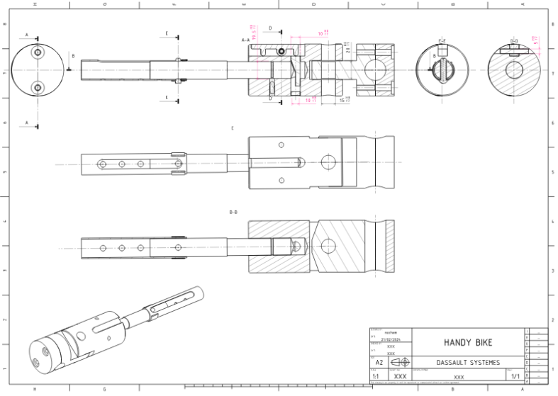
Initial functional plans to capture constraints.
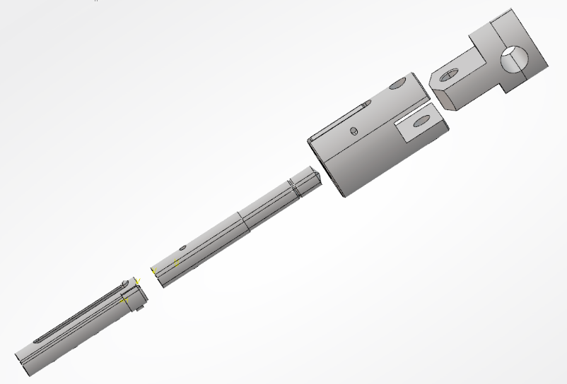
3D modeling in CATIA.
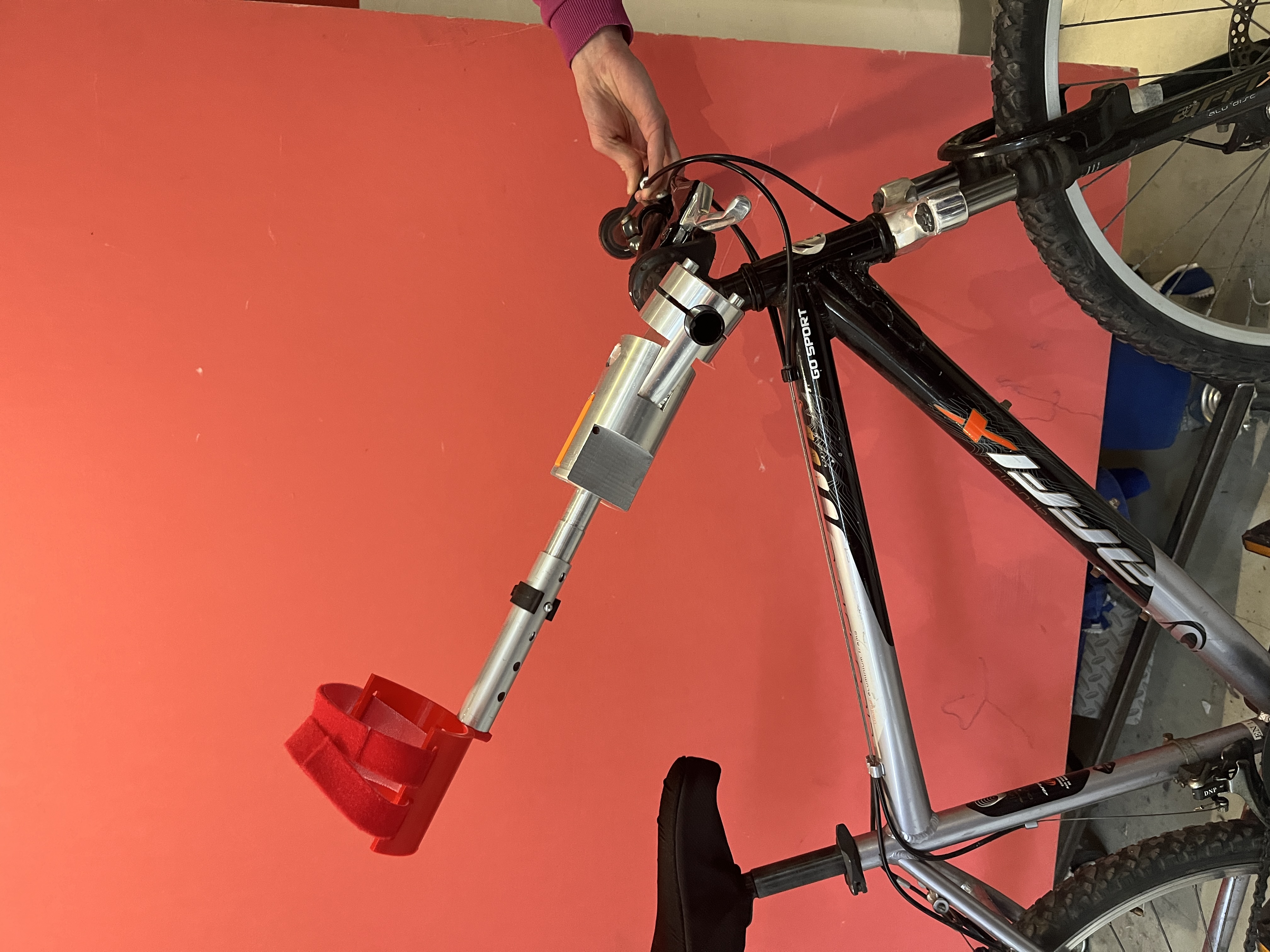
Final manufactured prosthesis.
Objectives
- Length-adjustable, multi-patient adaptability
- Secure attachment to the bike and forearm
- Safety in case of fall, easy detachment
- Balance, stability, modularity
My Role
- Design of the bike/forearm link system
- Functional sketches, CATIA modeling, manufacturing drawings
- Geometry optimization, mechanical integration with team
Methodology
- Client exchanges, survey of existing solutions
- Decision matrix, calculations, CAD, drawings
- Fabrication: 3D printing, machining
Technologies & Tools
Software: CATIA V6, Excel, Word.
Machines: Lathe, milling machine, 3D printer.
Sizing: Strength of materials, simulations.
Lessons Learned
Project management, advanced CAD, assisted fabrication, collaborative work.
Ecological and Societal Transition Challenge
Context & Stakes
Team project: making heavy trucks more ecological via electric supply using highway catenaries (pantograph system).
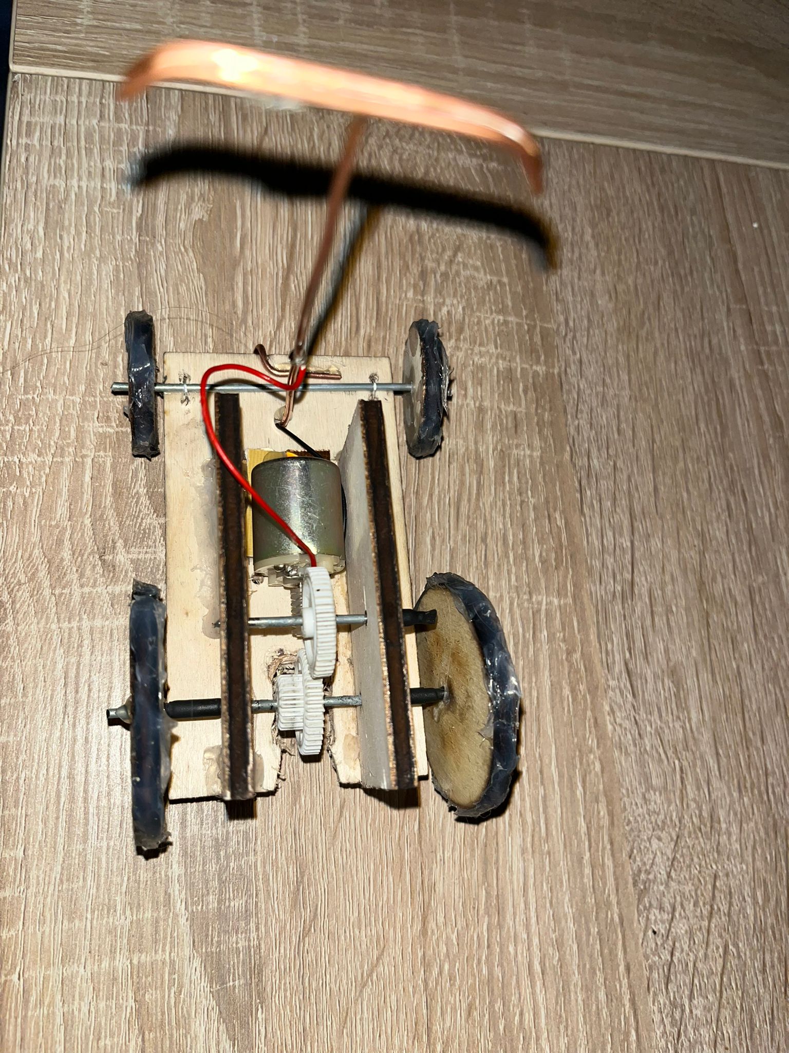
Prototype – top view
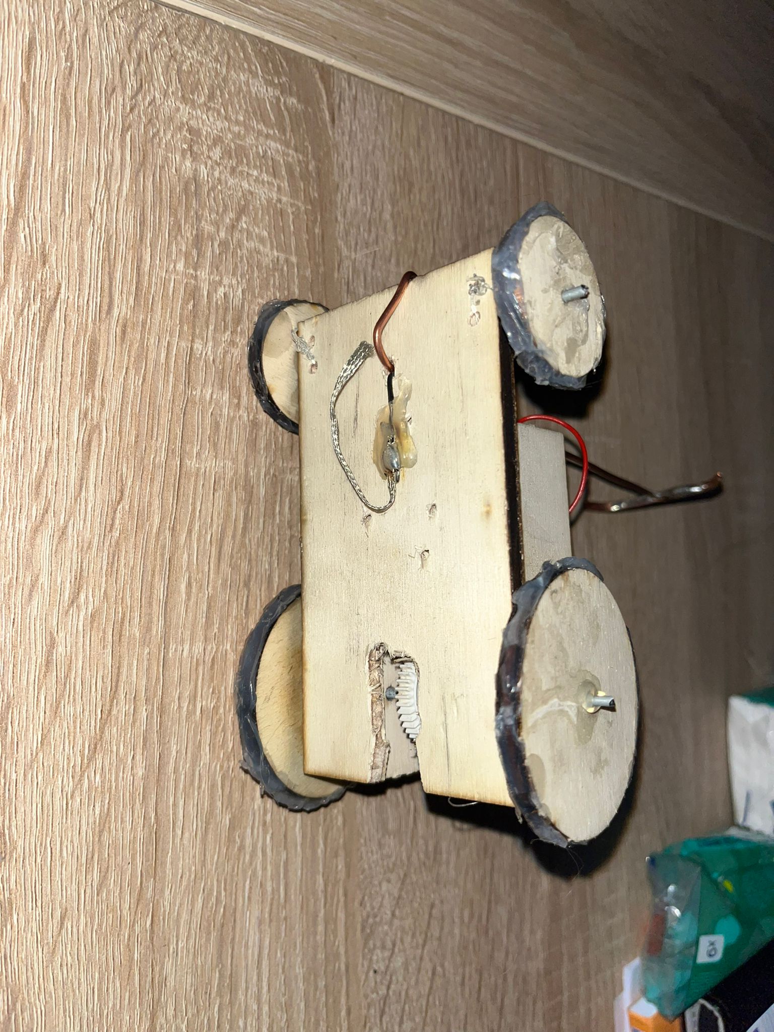
Prototype – bottom view
Objectives
- Reduce pollutant emissions of heavy transport
- Design an energy capture prototype
- Assess feasibility and environmental impact
My Role
- Design & fabrication of the laser-cut wooden mock-up
- Re-use of salvaged components
- Presentation & multi-disciplinary restitution
Methodology
- Brainstorming on transport solutions
- Technical & environmental evaluation
- Low-cost physical mock-up
Technologies & Tools
Machines: Laser cutter, multimeter, salvaged components.
Software: Canva, PowerPoint, spreadsheets.
Lessons Learned
First eco-design approach; importance of communication and cross-disciplinary management.
Electric Knife Project
Context & Stakes
Complete mechanical study and modeling of a domestic electric knife. Kinematic analysis, transformation of motor rotation into blade reciprocation, and 3D visualization.
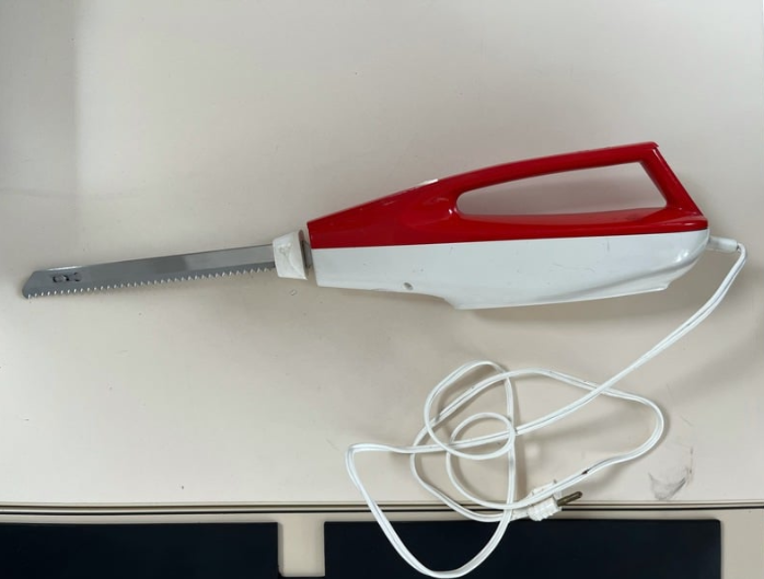
Starting point: disassembly and observation of parts.
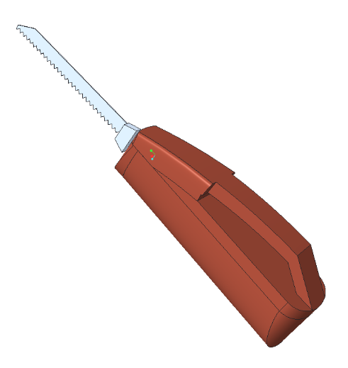
Reconstructed mechanism modeled in Creo Parametric.
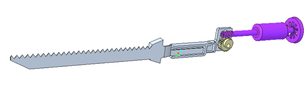
Modeled internal mechanical system.
Objectives
- Model parts in Creo Parametric
- Analyze kinematic operation
- Illustrate the system with an animation
My Role
- Kinematic analysis and complete modeling
- Mechanism animation in Creo
Methodology
- Disassembly, component identification
- Link analysis, precise measurements
- 3D modeling, animation, validation
Technologies & Tools
Software: Creo Parametric.
Tools: Caliper, ruler.
Hardware: Real device analyzed.
Lessons Learned
Mastery of 3D modeling, kinematic analysis, animation, and teamwork.
English Project / F1 Board Game
Context & Stakes
Team language project: creation of a Formula 1 board game inspired by Trivial Pursuit (design, rules, physical build, playable in class).
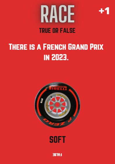
Easy
Medium
Hard
Objectives
- Create an original game
- Improve English through a fun project
- Build a fully playable game
My Role
- Defined the medium and rules
- Wrote and classified questions
Methodology
- Choose the medium
- Rules, questions, printing, 3D pawns
Technologies & Tools
Machines: 3D printer, regular printer, laminator.
Software: 3D printing software, Canva.
Lessons Learned
Teamwork, communication, rigor, creativity, pedagogy.
Checkerboard Robot Project
Context & Stakes
Team of 4: autonomous robot moving on a chessboard, grabbing and returning an object while avoiding obstacles. Programming, design, modeling, tests.
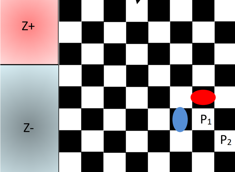
Board with mission zones and obstacles.
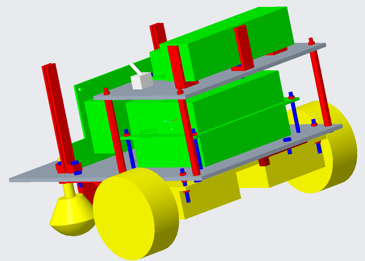
Rear 3/4 view of the model.
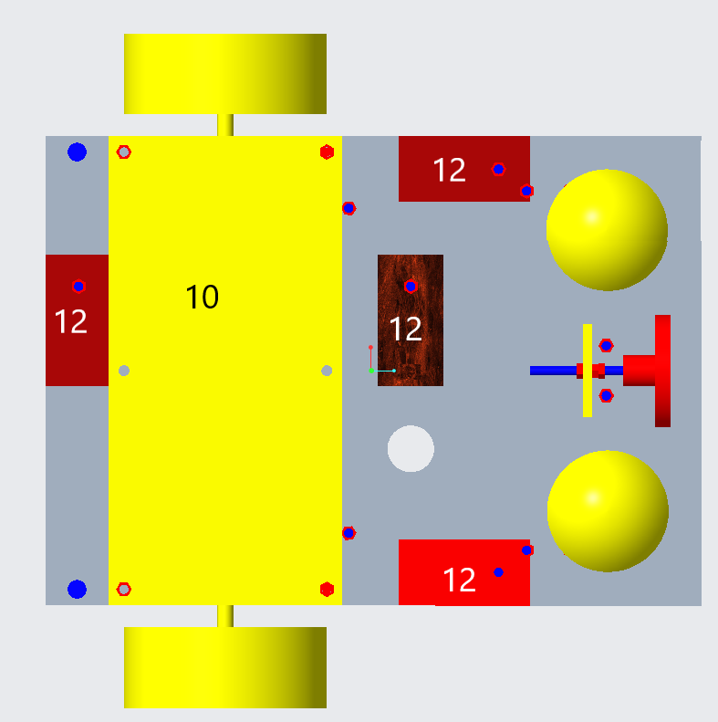
Bottom view with sensor placement.
Objectives
- Develop a reliable hook to tow the object
- Program autonomous path following
- Optimize line/obstacle detection
My Role
- Component choice, assembly, CAD
- Code development & sensor integration
Methodology
- Technical choices, CAD, assembly, tests
- Embedded programming, debugging
Technologies & Tools
Software: Visual Studio Code, component diagram tools.
Hardware: Arduino, sensors, motors, breadboard, etc.
Lessons Learned
Embedded programming, sensor integration, teamwork, rigorous testing.